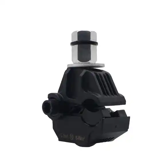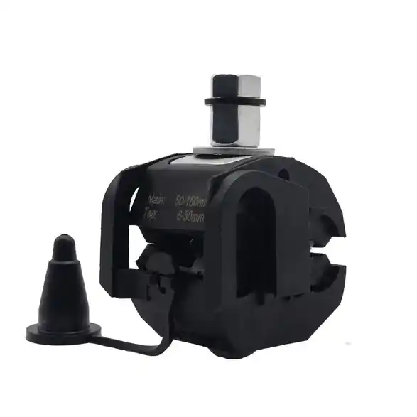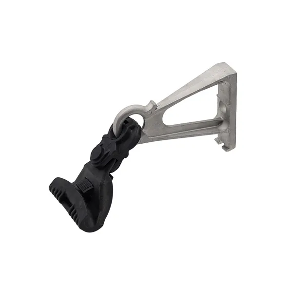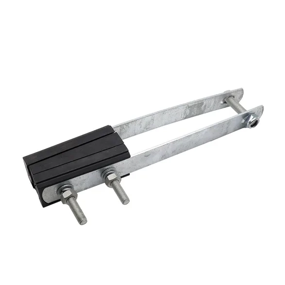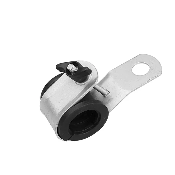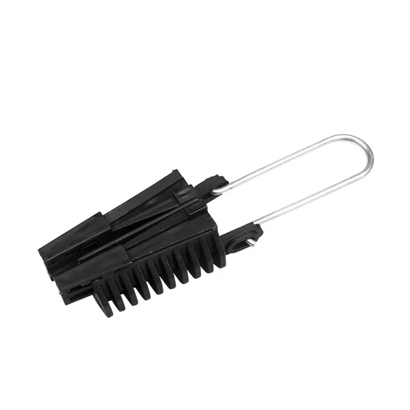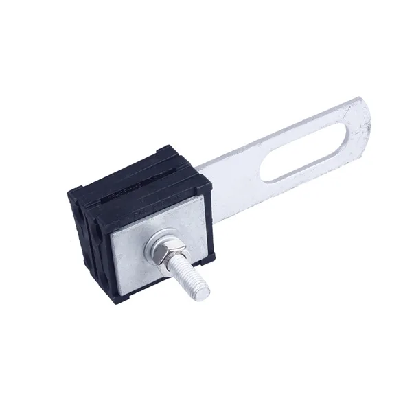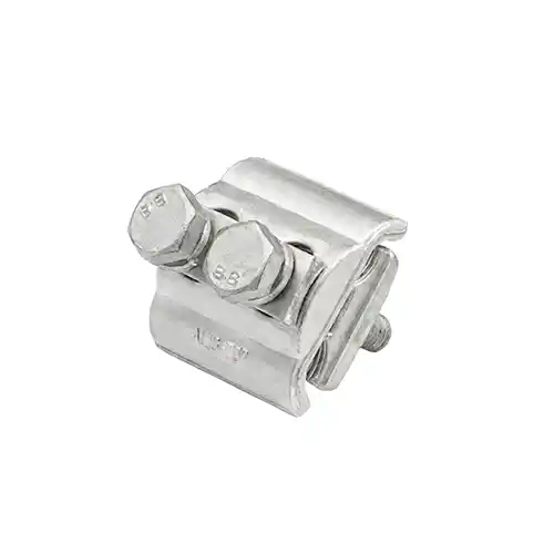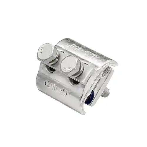
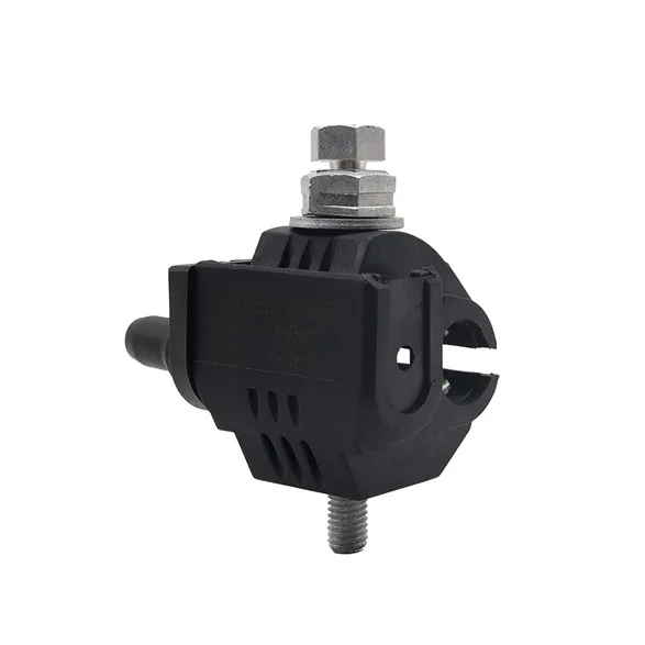
Insulation Piercing Connector (Bare Network Type) is robustly engineered for high-current transition splicing between bare overhead main lines (AAC/ACSR) and large-cross-section insulated network distribution cables. It establishes an uncompromised, permanent electrical node capable of handling immense trunk-line thermal and mechanical loads without damaging the bare main wire.
ContactSpecifications
| Part No. | Item | Mains Insulated Al-Cu mm² |
Tap Insulated Al-Cu mm² |
Number of Bolts |
| B010132 | IPCN-2 | 7-100 | 25-95 | 1 |
Features
High-Current Transition Matrix
Specifically engineered with a massive, flat-surface clamping jaw on the bare main side to maximize contact area, and reinforced piercing segments on the insulated tap side to carry continuous heavy network currents.
Single-Bolt Streamlined Efficiency
Features a heavy-duty single-shear-bolt architecture that concentrates mechanical force uniformly across the plates, guaranteeing a low-resistance contact with an optimized, compact footprint.
Potential-Free Hot-Line Safety
The single metallic shear bolt is entirely insulated and decoupled from live contact internals, ensuring comprehensive flashover protection and absolute linesman safety during energized network integration.
Advanced Moisture & Gas Seal
The insulated piercing housing is pre-filled with high-viscosity synthetic grease and lined with elastomeric seals, providing an encapsulated, watertight environment that eliminates galvanic oxidation at the bare-to-insulated interface.
Implementation Instructions
Step 1: Parallel Line Alignment
Fit the open, smooth channel of the connector over the bare mainline conductor. Simultaneously, feed the unstripped, insulated network branch cable into the piercing chamber until it is fully seated.
Step 2: Single-Bolt Torque Drive
Stabilize the connector body. Using an appropriate insulated spanner, tighten the single shear bolt steadily until the calibrated shear head snaps off completely, ensuring perfect contact pressure in a single operation.
Step 3: End Sealing Deployment
Verify that the integrated weather-resistant flexible end cap completely encloses the exposed tip of the insulated branch wire, providing a permanent barrier against water wicking and wildlife.
Step 4: Live-Line Network Safe Operation
Thanks to the fully potential-free single-bolt architecture, implementation can be safely executed on live bare networks (hot-line operation). However, to eliminate any potential for arcing during heavy network transition splicing, it is highly recommended to perform installation when there is no operational load running on the branching line.
Industrial Engineering & Standards
Designed and rigorously tested to withstand the extreme environmental and systemic stresses of global electrical utility networks:
- Premium Core Metallurgy: Jaws are precision-machined from elite-grade, high-conductivity tinned copper or tempered aluminium alloy, ensuring zero power loss and long-term contact stability.
- Full Standard Compliance: Engineered, batch-tested, and fully certified to comply with the elite international performance criteria of NF C 33-020 and EN 50483.
- 6kV Dielectric Flashover Isolation: The overall structural body guarantees robust electrical isolation, successfully passing rigorous dielectric breakdown tests exceeding 6 kV when completely submerged in water.