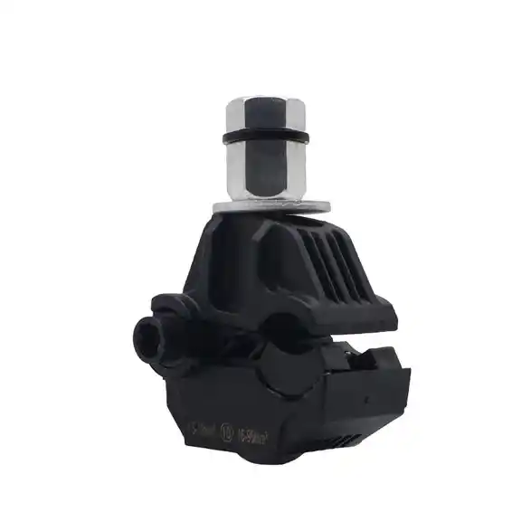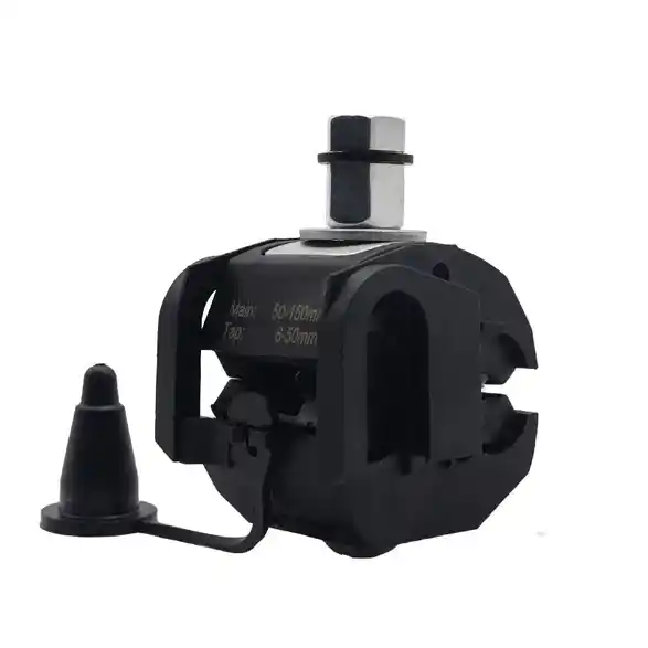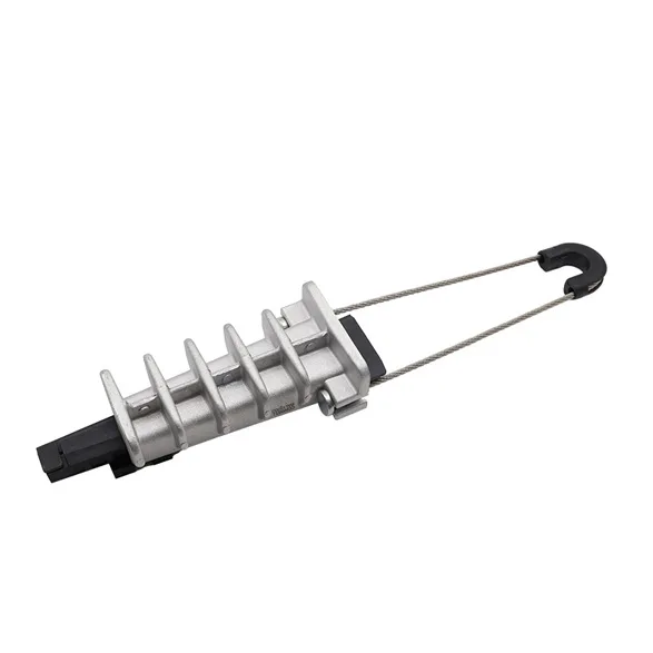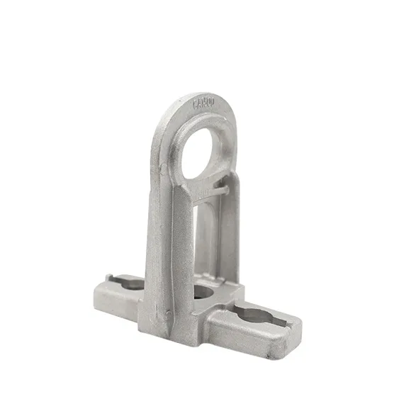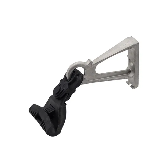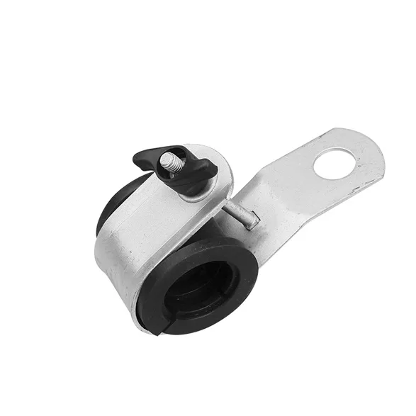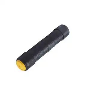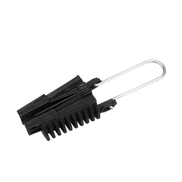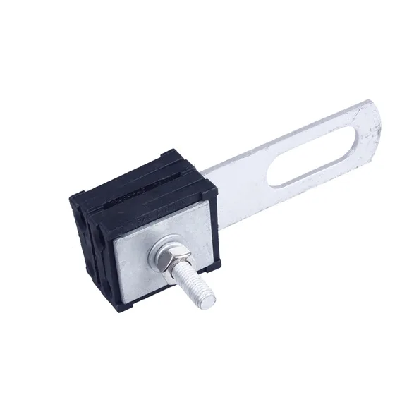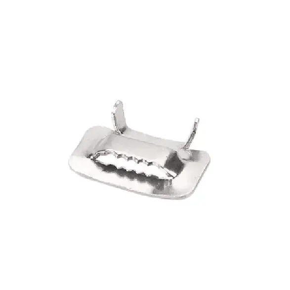
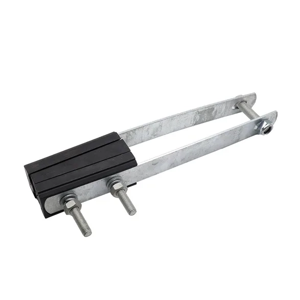
These heavy-duty Anchoring Clamps are explicitly engineered to secure and dead-end low-voltage Aerial Bundled Conductor (A.B.C.) bundles in fully supported (self-supporting) networks. Unlike messenger-wire systems, this clamp simultaneously grips and distributes the mechanical pulling forces uniformly across all four insulated phase conductors. This ensures an uncompromised, high-tension termination at end poles, heavy angled spans, and high-sag distribution positions without breaching the outer dielectric jacket of any cable core.
ContactSpecifications
| Part No. | Item | Cable Size mm² |
Cable Diameter (mm) |
Tensile Strength kN |
| B010701 | AC-1 | 4 x 16-50 | 7-11 | 20 |
| B010702 | AC-2 | 4 x 50-120 | 11-16 | 20 |
Features
Synchronized 4-Core Conical Clamping
Features an expansive wedge matrix designed to clamp all four insulated network conductors simultaneously. The internal conically-guided sliding blocks automatically lock tighter as the span’s mechanical deadweight and tension increase.
Heavy-Duty Weatherproof Shell
Built with a high-strength casing designed to resist intense atmospheric tracking, extreme wind shear, and continuous mechanical stress, maintaining network stability over decades of outdoor service.
Tool-Free Operational Simplicity
Designed with an innovative tool-less locking mechanism. The movable wedge blocks slide freely along the inner tracks, allowing linesmen to position and anchor the entire core bundle in a single, streamlined action.
Dielectric Core Protection
The internal gripping teeth and contact profiles are precision-molded from UV-stabilized, glass-fiber reinforced polymer. This provides maximum high-fatigue retention while completely eliminating localized stress concentration or insulation tearing.
Implementation Instructions
Step 1: Core Grouping & Insertion
Open the clamp housing or loosen the integrated retaining link. Separate and group the four insulated phase conductors of the bundle, feeding them neatly into the parallel slots of the internal sliding wedges.
Step 2: Bracket Hook Attachment
Engage the high-tensile steel loop or flexible wire bail over the pole crossarm hook or anchoring bracket. Ensure the wear-resistant protective saddle rests squarely on the hook to absorb mechanical friction.
Step 3: Self-Locking Tensioning
Apply mechanical pulling force to the bundle using standard stringing equipment to set the proper line sag. Push the insulating wedges firmly forward into the conical sleeve to engage the permanent, symmetric self-tightening grip before releasing the load.
Step 4: Full-Weight Stringing Safety Operation
Because fully supported 4-core networks carry substantial deadweight across all phases, linesmen must deploy proper sagging equipment, pulling socks, and temporary come-along tools to absorb the full mechanical tension of the overhead span before seating and locking the final bundle inside the anchoring wedges.
Industrial Engineering & Standards
High-performance mechanical fittings engineered to surpass the stringent stress, fatigue, and environmental requirements of international utility distribution grids:
- Premium Material Engineering: Constructed from structural-grade, corrosion-free aluminium alloy or hot-dip galvanized steel bails, combined with weather-proof, impact-resistant industrial thermoplastics.
- Rigid Industrial Compliance: Fully compliant and thoroughly qualified according to the demanding mechanical tension and climatic testing criteria of NF C 33-042 and EN 50483-3 standards.
- Zero Thermal Degradation: The engineered polymer components maintain exceptional structural rigidity and chemical resilience across an expansive operational temperature spectrum from extreme sub-zero conditions to intense tropical heat waves.