
- For branching conductor
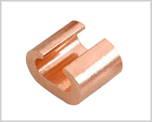
- Material: Copper
- Surface: Bright or Tin plated to protect against corrosion
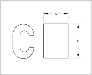
| Part No. | Item | Cross Section | Main Dimensions (mm) | |||||
| (Main + Tap) mm² | H | A | B | L | C | T | ||
| A020701 | CC-10 | 7.5-14 | 9.5 | 6.3 | 6.2 | 12.0 | 4.0 | 1.6 |
| A020702 | CC-16 | 14.5-16 | 11.8 | 7.8 | 7.8 | 13.0 | 5.0 | 2.0 |
| A020703 | CC-20 | 16.5-20 | 12.8 | 8.6 | 9.7 | 13.0 | 5.4 | 2.9 |
| A020704 | CC-26 | 21-26 | 14.7 | 10.2 | 10.0 | 16.0 | 6.5 | 3.2 |
| A020705 | CC-44 | 27-44 | 19.0 | 13.4 | 14.4 | 20.0 | 8.5 | 4.0 |
| A020706 | CC-60 | 45-60 | 21.0 | 15.4 | 15.4 | 22.0 | 9.7 | 4.0 |
| A020707 | CC-76 | 61-76 | 24.4 | 17.3 | 17.6 | 22.0 | 10.8 | 5.0 |
| A020708 | CC-98 | 77-98 | 27.8 | 20.8 | 18.8 | 25.0 | 12.8 | 5.0 |
| A020709 | CC-122 | 99-122 | 29.8 | 22.1 | 21.2 | 26.0 | 13.5 | 5.5 |
| A020710 | CC-154 | 123-154 | 34.0 | 25.7 | 24.4 | 28.0 | 17.0 | 6.0 |
| A020711 | CC-190 | 155-154 | 37.0 | 28.5 | 25.4 | 35.0 | 17.4 | 6.0 |
| A020712 | CC-240 | 191-240 | 40.0 | 30.2 | 28.5 | 40.0 | 19.0 | 7.0 |
| A020713 | CC-288 | 141-288 | 44.5 | 34.7 | 34.1 | 45.0 | 22.3 | 7.0 |
| A020714 | CC-365 | 189-365 | 47.5 | 37.7 | 34.0 | 50.0 | 24.8 | 7.0 |
| A020715 | CC-450 | 366-450 | 57.0 | 42.5 | 41.0 | 60.0 | 28.0 | 10.0 |
| A020716 | CC-560 | 451-560 | 62.0 | 46.0 | 44.0 | 65.0 | 31.0 | 11.0 |
| A020717 | CC-700 | 561-700 | 68.0 | 54.0 | 49.5 | 70.0 | 44.0 | 12.0 |
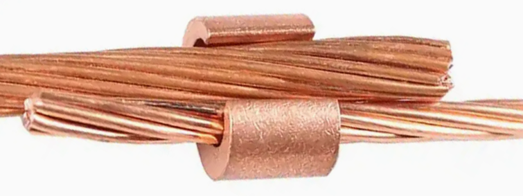
Copper C-Cable Clamps (often referred to as C-Taps) are essential compression connectors used primarily for tapping into or splicing continuous run electrical conductors. Known for their distinct “C” shape, these components are engineered to provide a high-pressure, low-resistance connection that ensures long-term electrical stability.
Key Applications
Copper C-clamps are favored in industries where reliability is non-negotiable. Their primary uses include:
1. Grounding and Bonding Systems
This is perhaps the most common application. C-clamps are used to connect ground wires to ground rods or to create a grid of conductors (grounding mats) under substations. Because they are made of high-conductivity copper, they ensure that surge currents are safely diverted to the earth.
2. Power Distribution Tapping
In industrial settings, C-clamps allow electricians to “tap” into a main feeder line to provide power to a secondary circuit without cutting the primary conductor. This maintains the physical integrity of the main line while expanding the distribution network.
3. Lightning Protection
Buildings and towers use C-taps to connect lightning rods to down-conductors. The compression fitting is vital here, as it must withstand the massive thermal and mechanical stress of a lightning strike without loosening.
4. Cathodic Protection
In the oil, gas, and water industries, C-clamps are used to connect sacrificial anodes to pipelines. This helps prevent corrosion by ensuring a consistent electrical bond between the pipe and the protection system.
Advantages of Using C-Clamps
Space Efficiency: Their compact design allows them to be used in tight spaces like junction boxes or cable trays where bulky mechanical bolt connectors won’t fit.
Permanent Connection: Once crimped with the proper hydraulic tool, the connection is nearly as strong as the wire itself.
Corrosion Resistance: Made from high-grade electrolytic copper, they resist oxidation, especially when used with an oxide inhibitor compound.
Installing a copper C-clamp is a “permanent” connection process. Unlike mechanical lugs that use screws, C-taps rely on compression (crimping) to create a cold-weld bond between conductors. Following the correct procedure is vital to ensure low resistance and prevent overheating.
Tools and Materials Needed
- Copper C-Clamps: Sized correctly for your “Run” and “Tap” wires.
- Compression Tool: A manual or hydraulic crimper (e.g., a “Burndy” style tool).
- Matching Dies: The specific metal inserts for the tool that match the clamp size.
- Wire Strippers/Cable Cutters.
- Wire Brush: To clean the conductors.
- Oxide Inhibitor: A conductive paste to prevent corrosion.
Step-by-Step Installation Process
1. Sizing and Selection
Check the markings on the C-clamp. It will list a range for the Run (the main continuous wire) and the Tap (the wire branching off).
Example: A clamp marked “Run 2-6 / Tap 8-14” means the main wire can be between 2 and 6 AWG, and the branch wire between 8 and 14 AWG.
2. Prepare the Conductors
- Strip the Insulation: Remove enough insulation from both wires so the bare copper fits completely within the “C” opening. Avoid nicking the copper strands.
- Clean the Copper: Even if the wire looks shiny, use a stainless steel wire brush to scrub the surface. This removes invisible oxides that increase electrical resistance.
3. Apply Oxide Inhibitor
Coat the cleaned bare wires with a high-quality conductive antioxidant paste. This is especially critical in outdoor or high-humidity environments to prevent the connection from degrading over time.
4. Position the Clamp
Place the Run wire into the deeper part of the “C” and the Tap wire into the smaller curve. Ensure both wires are seated firmly against the back of the clamp.
5. Execute the Compression
- Select the correct die as specified by the clamp manufacturer (often color-coded).
- Place the clamp inside the jaws of the compression tool.
- Activate the tool (pump the handle or trigger) until the tool bypasses or completes its cycle. Partial crimps are a fire hazard.
6. Final Inspection
A proper crimp will leave the die index number embossed on the surface of the copper. Check that:
- The clamp is deformed uniformly.
- The wires are tight and cannot be moved or rotated.
- There is no “flashing” (excess metal squeezed out) that could interfere with insulation taping.
Safety Best Practices
- Never Reuse: C-clamps are one-time-use connectors. Once compressed, the metal has been “work-hardened” and cannot be safely undone or reused.
- Insulation: After installation, if the connection is not for a grounding system, it must be properly insulated using heat-shrink tubing or high-voltage rubber and friction tape.
- Die Matching: Never “guess” the die size. Using a die that is too large results in a loose connection; a die too small can crack the connector.