
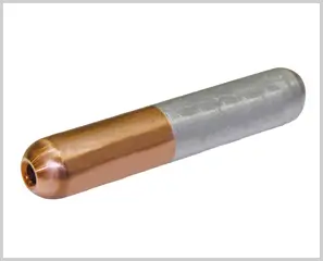
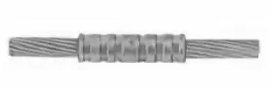
- Friction welding
- Manufactured according to EDF HN 68 S 90
- Material: Copper, Aluminium
- Surface: Bright
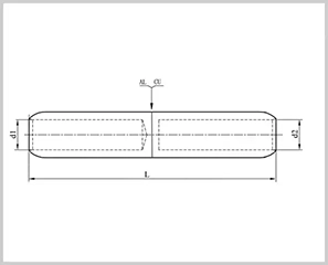
| Part No. | Item | Cross Section Al/Cu mm² |
Dimensions(mm) | ||
| d1 | d2 | L | |||
| A060101 | RJAU-16/16 | 16/16 | 6.0 | 6.0 | 91.0 |
| A060102 | RJAU-25/16 | 25/16 | 7.0 | 6.0 | 91.0 |
| A060103 | RJAU-25/25 | 25/25 | 8.0 | 7.5 | 91.0 |
| A060104 | RJAU-35/16 | 35/16 | 8.5 | 6.0 | 107.0 |
| A060105 | RJAU-35/25 | 35/25 | 8.5 | 7.0 | 107.0 |
| A060106 | RJAU-35/35 | 35/35 | 8.5 | 8.5 | 107.0 |
| A060107 | RJAU-50/25 | 50/25 | 9.7 | 7.0 | 107.0 |
| A060108 | RJAU-50/35 | 50/35 | 9.7 | 8.5 | 107.0 |
| A060109 | RJAU-50/50 | 50/50 | 9.7 | 9.7 | 107.0 |
| A060110 | RJAU-70/35 | 70/35 | 11.5 | 8.5 | 107.0 |
| A060111 | RJAU-70/50 | 70/50 | 11.5 | 9.7 | 107.0 |
| A060112 | RJAU-70/70 | 70/70 | 11.5 | 11.5 | 107.0 |
| A060113 | RJAU-95/35 | 95/35 | 13.5 | 8.5 | 107.0 |
| A060114 | RJAU-95/50 | 95/50 | 13.5 | 9.7 | 107.0 |
| A060115 | RJAU-95/70 | 95/70 | 13.5 | 11.5 | 133.0 |
| A060116 | RJAU-95/95 | 95/95 | 13.5 | 13.5 | 133.0 |
| A060117 | RJAU-120/50 | 120/50 | 15.0 | 9.7 | 133.0 |
| A060118 | RJAU-120/70 | 120/70 | 15.0 | 11.5 | 133.0 |
| A060119 | RJAU-120/95 | 120/95 | 15.0 | 13.5 | 133.0 |
| A060120 | RJAU-120/120 | 120/120 | 15.0 | 15.0 | 133.0 |
| A060121 | RJAU-150/50 | 150/50 | 16.5 | 9.7 | 133.0 |
| A060122 | RJAU-150/70 | 150/70 | 16.5 | 11.5 | 133.0 |
| A060123 | RJAU-150/95 | 150/95 | 16.5 | 13.5 | 133.0 |
| A060124 | RJAU-150/120 | 150/120 | 16.5 | 15.0 | 133.0 |
| A060125 | RJAU-150/150 | 150/150 | 16.5 | 16.5 | 133.0 |
| A060126 | RJAU-185/95 | 185/95 | 18.5 | 13.5 | 143.5 |
| A060127 | RJAU-185/120 | 185/120 | 18.5 | 15.0 | 143.5 |
| A060128 | RJAU-185/150 | 185/150 | 18.5 | 16.5 | 143.5 |
| A060129 | RJAU-185/185 | 185/185 | 18.5 | 18.5 | 143.5 |
| A060130 | RJAU-240/150 | 240/150 | 21.0 | 16.5 | 143.5 |
| A060131 | RJAU-240/185 | 240/185 | 21.0 | 18.5 | 143.5 |
| A060132 | RJAU-240/240 | 240/240 | 21.0 | 21.0 | 143.5 |
| A060133 | RJAU-300/240 | 300/240 | 23.0 | 21.0 | 180.0 |
| A060134 | RJAU-300/300 | 300/300 | 23.0 | 23.0 | 180.0 |
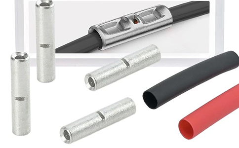
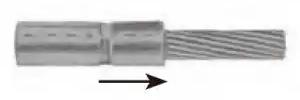
Connecting two wires end-to-end is a fundamental task in electrical work, primarily achieved through a method known as a butt splice. This type of connection is designed to maintain the continuity of the circuit while ensuring the joint is mechanically secure and electrically insulated.
Whether you are repairing a broken lead or extending a wiring run, here is a breakdown of how these connectors function and the common types used.
What is a Butt Connector?
A butt connector is a cylindrical tube—usually made of copper or brass and plated with tin—that allows two wires to be inserted from opposite ends. Once the wires meet in the middle, the connector is “crimped” (compressed) to lock them in place.
Common Types of End-to-End Connectors
- Insulated Crimp Connectors: The most common variety, featuring a color-coded plastic sleeve (Red, Blue, or Yellow) that indicates the wire gauge it can accept.
- Heat Shrink Butt Connectors: These include an adhesive-lined sleeve that, when heated, shrinks around the wire insulation. This provides a waterproof seal and superior strain relief, making them ideal for automotive or marine environments.
- Solder Sleeve Connectors: A “no-crimp” high-tech option. These contain a ring of low-temperature solder inside a heat-shrink tube. Using a heat gun melts the solder and shrinks the tubing simultaneously, creating a soldered, insulated joint in one step.
- Step-Down Connectors: Specifically designed to connect two wires of different sizes (e.g., joining a 12-gauge wire to a 16-gauge wire).
Key Advantages
Safety: The integrated insulation prevents the bare wire from shorting against other components or the housing.
Space Efficiency: Unlike twist-on wire nuts, butt connectors are slim and stay inline with the wire, making them perfect for tight conduits or wiring harnesses.
Durability: A proper crimp creates a “cold weld,” which is highly resistant to vibration and pulling.
Based on the technical guidelines provided, here is a structured guide to performing a professional-grade end-to-end compression connection (butt splice).
1. The Principle of Compression
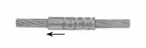
For a connection to be durable and heavy-duty, there must be a precise match between the conductor size, the joint sleeve, and the crimping die. When done correctly, the resulting hexagonal compression is rated for temperatures up to 90°C.
2. Preparation & Selection
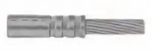
Before starting, identify the markings stamped on the compression joint. These typically include:
- Cross-section specification (e.g., wire gauge/mm²).
- Manufacturer’s logo.
- Die code number (correlates to the outer diameter of the sleeve).
Tooling Requirements:
- Mechanical Tools: Use “Cu” marked dies for copper/steel and “Al” dies for aluminum.
- Hydraulic Tools: Differentiation between material types is generally not required.
3. Step-by-Step Assembly
Follow these steps to ensure electrical continuity and mechanical strength:
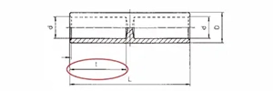
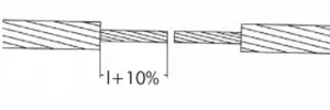
- Strip: Remove insulation to the length of the sleeve +10%.
- Clean: Remove all tapes, yarn, or powder. Use a metal brush to erase dirt and oxide layers from the bare conductors.
- Insert: Push the first conductor into the sleeve until it hits the center stop or is visible in the inspection hole.
- Verify: Double-check that the die code in your tool matches the mark on the joint.
- Compress (Side A): Start from the middle and move toward the barrel end. Note: You must compress every marking indicated on the sleeve.
- Repeat (Side B): Insert the second conductor and repeat the compression sequence from the middle outward.
4. Final Quality Check
- Extension: A successful compression will typically cause the joint to elongate by approximately 10%.
- Cleanup: Wipe away any excess grease squeezed out during the process.
- Special Cases: Always refer to specific manuals for notch-type midspan joints or connectors with steel sleeves, as they have unique requirements.