
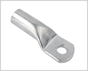
- Manufactured according to DIN46235
- With marking for correct crimping
- Material: Copper
- Surface: Tin plated to protect against corrosion
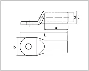
| Part No. | Item | Cross Section mm² |
Size of Bolt Φ |
Dimensions(mm) | ||||
| D | d | a | b | L | ||||
| A010101 | DCL 6-5 | 6 | M 5 | 5.5 | 3.8 | 10.0 | 8.5 | 30.5 |
| A010102 | DCL 6-6 | M 6 | 5.5 | 3.8 | 10.0 | 8.5 | 31.5 | |
| A010103 | DCL 6-8 | M 8 | 5.5 | 3.8 | 10.0 | 13.0 | 34.0 | |
| A010104 | DCL 10-5 | 10 | M 5 | 6.0 | 4.5 | 10.0 | 9.0 | 34.0 |
| A010105 | DCL 10-6 | M 6 | 6.0 | 4.5 | 10.0 | 9.0 | 34.5 | |
| A010106 | DCL 10-8 | M 8 | 6.0 | 4.5 | 10.0 | 13.0 | 37.0 | |
| A010107 | DCL 10-10 | M 10 | 6.0 | 4.5 | 10.0 | 15.0 | 39.0 | |
| A010108 | DCL 16-6 | 16 | M 10 | 8.5 | 5.5 | 20.0 | 13.0 | 43.5 |
| A010109 | DCL 16-8 | M 8 | 8.5 | 5.5 | 20.0 | 13.0 | 46.0 | |
| A010110 | DCL 16-10 | M 10 | 8.5 | 5.5 | 20.0 | 17.0 | 48.0 | |
| A010111 | DCL 16-12 | M 12 | 8.5 | 5.5 | 20.0 | 18.0 | 49.0 | |
| A010112 | DCL 25-6 | 25 | M 6 | 10.0 | 7.0 | 20.0 | 14.0 | 45.5 |
| A010113 | DCL 25-8 | M 8 | 10.0 | 7.0 | 20.0 | 16.0 | 48.0 | |
| A010114 | DCL 25-10 | M 10 | 10.0 | 7.0 | 20.0 | 17.0 | 50.0 | |
| A010115 | DCL 25-12 | M 12 | 10.0 | 7.0 | 20.0 | 19.0 | 51.0 | |
| A010116 | DCL 35-6 | 35 | M 6 | 12.5 | 8.2 | 20.0 | 17.0 | 49.5 |
| A010117 | DCL 35-8 | M 8 | 12.5 | 8.2 | 20.0 | 17.0 | 52.0 | |
| A010118 | DCL 35-10 | M 10 | 12.5 | 8.2 | 20.0 | 19.0 | 54.0 | |
| A010119 | DCL 35-12 | M 12 | 12.5 | 8.2 | 20.0 | 21.0 | 55.0 | |
| A010120 | DCL 35-14 | M 14 | 12.5 | 8.2 | 20.0 | 21.0 | 56.5 | |
| A010121 | DCL 50-8 | 50 | M 8 | 14.5 | 10.0 | 28.0 | 20.0 | 62.0 |
| A010122 | DCL 50-10 | M 10 | 14.5 | 10.0 | 28.0 | 22.0 | 64.0 | |
| A010123 | DCL 50-12 | M 12 | 14.5 | 10.0 | 28.0 | 24.0 | 65.0 | |
| A010124 | DCL 50-14 | M 14 | 14.5 | 10.0 | 28.0 | 24.0 | 66.5 | |
| A010125 | DCL 50-16 | M 16 | 14.5 | 10.0 | 28.0 | 28.0 | 68.0 | |
| A010126 | DCL 70-8 | 70 | M 8 | 16.5 | 11.5 | 28.0 | 24.0 | 65.0 |
| A010127 | DCL 70-10 | M 10 | 16.5 | 11.5 | 28.0 | 24.0 | 67.0 | |
| A010128 | DCL 70-12 | M 12 | 16.5 | 11.5 | 28.0 | 24.0 | 68.0 | |
| A010129 | DCL 70-14 | M 14 | 16.5 | 11.5 | 28.0 | 24.0 | 69.5 | |
| A010130 | DCL 70-16 | M 16 | 16.5 | 11.5 | 28.0 | 30.0 | 71.0 | |
| A010131 | DCL 95-8 | 95 | M 8 | 19.0 | 13.5 | 35.0 | 28.0 | 77.0 |
| A010132 | DCL 95-10 | M 10 | 19.0 | 13.5 | 35.0 | 28.0 | 77.0 | |
| A010133 | DCL 95-12 | M 12 | 19.0 | 13.5 | 35.0 | 28.0 | 78.0 | |
| A010134 | DCL 95-14 | M 14 | 19.0 | 13.5 | 35.0 | 28.0 | 79.5 | |
| A010135 | DCL 95-16 | M 16 | 19.0 | 13.5 | 35.0 | 32.0 | 81.0 | |
| A010136 | DCL 120-10 | 120 | M 10 | 21.0 | 15.5 | 35.0 | 32.0 | 85.0 |
| A010137 | DCL 120-12 | M 12 | 21.0 | 15.5 | 35.0 | 32.0 | 86.0 | |
| A010138 | DCL 120-14 | M 14 | 21.0 | 15.5 | 35.0 | 32.0 | 88.0 | |
| A010139 | DCL 120-16 | M 16 | 21.0 | 15.5 | 35.0 | 32.0 | 89.0 | |
| A010140 | DCL 120-20 | M 20 | 21.0 | 15.5 | 35.0 | 38.0 | 91.0 | |
| A010141 | DCL 150-10 | 150 | M 10 | 23.5 | 17.0 | 35.0 | 34.0 | 93.0 |
| A010142 | DCL 150-12 | M 12 | 23.5 | 17.0 | 35.0 | 34.0 | 94.0 | |
| A010143 | DCL 150-14 | M 14 | 23.5 | 17.0 | 35.0 | 34.0 | 97.0 | |
| A010144 | DCL 150-16 | M 16 | 23.5 | 17.0 | 35.0 | 34.0 | 97.0 | |
| A010145 | DCL 150-20 | M 20 | 23.5 | 17.0 | 35.0 | 40.0 | 99.0 | |
| A010146 | DCL 185-10 | 185 | M 10 | 25.5 | 19.0 | 40.0 | 37.0 | 97.0 |
| A010147 | DCL 185-12 | M 12 | 25.5 | 19.0 | 40.0 | 37.0 | 98.0 | |
| A010148 | DCL 185-14 | M 14 | 25.5 | 19.0 | 40.0 | 37.0 | 101.0 | |
| A010149 | DCL 185-16 | M 16 | 25.5 | 19.0 | 40.0 | 37.0 | 101.0 | |
| A010150 | DCL 185-20 | M 20 | 25.5 | 19.0 | 40.0 | 40.0 | 103.0 | |
| A010151 | DCL 240-12 | 240 | M 12 | 29.0 | 21.5 | 40.0 | 42.0 | 108.0 |
| A010152 | DCL 240-14 | M 14 | 29.0 | 21.5 | 40.0 | 42.0 | 111.0 | |
| A010153 | DCL 240-16 | M 16 | 29.0 | 21.5 | 40.0 | 42.0 | 111.0 | |
| A010154 | DCL 240-20 | M 20 | 29.0 | 21.5 | 40.0 | 45.0 | 113.0 | |
| A010155 | DCL 300-12 | 300 | M 12 | 32.0 | 24.5 | 50.0 | 46.0 | 119.0 |
| A010156 | DCL 300-14 | M 14 | 32.0 | 24.5 | 50.0 | 46.0 | 119.0 | |
| A010157 | DCL 300-16 | M 16 | 32.0 | 24.5 | 50.0 | 46.0 | 119.0 | |
| A010158 | DCL 300-20 | M 20 | 32.0 | 24.5 | 50.0 | 46.0 | 122.0 | |
| A010159 | DCL 400-14 | 400 | M 14 | 38.5 | 27.5 | 70.0 | 55.0 | 140.0 |
| A010160 | DCL 400-16 | M 16 | 38.5 | 27.5 | 70.0 | 55.0 | 140.0 | |
| A010161 | DCL 400-20 | M 20 | 38.5 | 27.5 | 70.0 | 55.0 | 140.0 | |
| A010162 | DCL 500-16 | 500 | M 16 | 42.0 | 31.0 | 70.0 | 60.0 | 150.0 |
| A010163 | DCL 500-20 | M 20 | 42.0 | 31.0 | 70.0 | 60.0 | 150.0 | |
| A010164 | DCL 625-16 | 630 | M 16 | 44.0 | 34.5 | 80.0 | 64.0 | 160.0 |
| A010165 | DCL 625-20 | M 20 | 44.0 | 34.5 | 80.0 | 64.0 | 160.0 | |
| A010166 | DCL 800-16 | 800 | M 16 | 52.0 | 40.0 | 100.0 | 75.0 | 195.0 |
| A010167 | DCL 800-20 | M 20 | 52.0 | 40.0 | 100.0 | 75.0 | 195.0 | |
| A010168 | DCL 1000-16 | 1000 | M 16 | 58.0 | 44.0 | 100.0 | 85.0 | 195.0 |
| A010169 | DCL 1000-20 | M 20 | 58.0 | 44.0 | 100.0 | 85.0 | 195.0 | |
Electrical lugs (also known as cable connectors) are the essential “middlemen” of the electrical world. They allow cables to be connected to devices or to other cables securely, even when a permanent weld isn’t possible.
Here is a simplified breakdown of what they are, how they work, and the different types available.
What is an Electrical Lug?
An electrical lug is a connector that ensures the smooth flow of electricity between cables and equipment. They are designed to make installation, repairs, and maintenance much easier.
How they work:
- Cable End: One end of the lug is attached to the wire by crimping (squeezing it tight), soldering, or welding.
- Device End: The other end is fastened to a terminal on an appliance or power source using a bolt, screw, or spring clip.
Common Types of Lugs
Lugs come in many shapes and materials depending on the industry (like automation, power distribution, or home appliances).
1. Terminal Lugs (General Industry)
Used widely in control panels and instrumentation. Common shapes include:
- Ring & Fork: For bolting onto terminals.
- Pin & Blade: For plugging into specific slots.
- Hook: For quick connections.
2. Butt and Parallel Connectors
These are specifically used to join two cables together or terminate them. They often come with insulation like:
- PVC Insulated: Standard protection.
- Heat Shrinkable: Shrinks around the wire for a waterproof seal.
- Closed-End: For capping off wires.
3. Heavy-Duty & High Voltage Lugs
In power plants or high-voltage lines, specialized lugs are required:
- Compression Lugs: Specifically for high-voltage cables.
- Copper Tubular Lugs: Thick-walled connectors designed to handle massive amounts of current.
Safety and Materials
- Insulation: Most lugs are wrapped in rubber or plastic. This prevents accidental shocks and ensures safe handling.
- Materials: Copper is the most popular material because it conducts electricity extremely well.
- Strength: For heavy-duty jobs, the mechanical strength of the lug is just as important as its electrical conductivity.
Key Takeaway
When choosing a lug, always match it to your cable size, the voltage level, and the environment (e.g., whether it needs heat-shrink insulation or extra heavy-duty copper).
This guide outlines the critical steps for creating a high-quality electrical connection using DIN Copper Compression Cable Lugs. Precision in matching components is the most important factor for safety and long-term durability.
1. Preparation and Selection
Before starting, ensure that the lug, conductor, and crimping die are all perfectly matched by size and material.
- Identification: Look for the cross-section specification (mm2) stamped directly on the DIN Copper Compression Cable Lugs.
- Die Selection: Use a die that matches the lug size.
- Material Matching:
- Use “Cu” marked dies for copper lugs.
- Use “Al” marked dies for aluminum or aluminum alloy lugs.
- Note: Hydraulic tools generally do not require different dies based on conductor material, provided the size is correct.
2. Conductor Preparation
A clean contact surface is essential to prevent resistance and overheating.
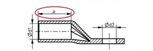
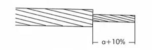
- Stripping: Strip the conductor insulation to the length of the sleeve plus an additional 10% (a + 10%).
- Cleaning: Remove any tape, yarn, or powder fillers. Use a metal brush to vigorously scrub away dirt and oxide layers from the bare conductor.
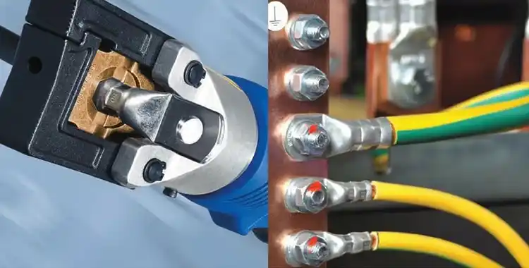
3. Assembly and Compression
The sequence of the crimp determines how the metal flows and secures the connection.
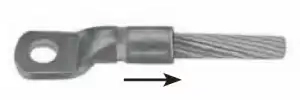
- Insertion: Insert the conductor into the sleeve until it hits the internal stop or is visible through the inspection hole.
- Verification: Double-check that the die code on your tool matches the size mark on the lug.
- Direction: Always start compressing from the palm side (the flat part with the hole) and work your way toward the barrel end (where the cable enters).
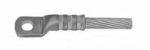
- Markings: Follow the marking lines on the lug. All indicated points must be compressed to ensure a full mechanical bond.
4. Final Quality Check
Once the compression is complete, perform a final inspection:
- Elongation: A correctly matched and compressed sleeve will typically extend in length by approximately 5%.
- Cleanliness: Wipe away any excess grease or joint compound that may have squeezed out during the process.